Product Description
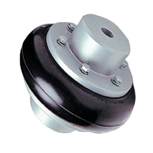
Aluminum Alloy GFC-55X49 Type Shaft Coupler Rubber Flexible Coupling
Aluminum Alloy GFC-55X49 Type Shaft Coupler Rubber Flexible Coupling
| model parameter | common bore diameter d1,d2 | ΦD | L | LF | LP | F | M | tightening screw torque (N.M) |
| GFC-14X22 | 3,4,5,6,6.35 | 14 | 22 | 14.3 | 6.6 | 5.0 | M2.5 | 1.0 |
| GFC-20×25 | 3,4,5,6,6.35,7,8,9,9.525,10 | 20 | 25 | 16.7 | 8.6 | 5.9 | M3 | 1.5 |
| GFC-20X30 | 3,4,5,6,6.35,7,8,9,9.525,10 | 20 | 30 | 19.25 | 8.6 | 5.9 | M3 | 1.5 |
| GFC-25X30 | 4,5,6,6.35,7,8,9,9.525,10,11,12 | 25 | 30 | 20.82 | 11.6 | 8.5 | M4 | 2.5 |
| GFC-25X34 | 4,5,6,6.35,7,8,9,9.525,10,11,12 | 25 | 34 | 22.82 | 11.6 | 8.5 | M4 | 2.5 |
| GFC-30×35 | 5,6,6.35,7,8,9,10,11,12,12.7,14,15,16 | 30 | 35 | 23 | 11.5 | 10 | M4 | 2.5 |
| GFC-30X40 | 5,6,6.35,7,8,9,10,11,12,12.7,14,15,16 | 30 | 40 | 25 | 11.5 | 10 | M4 | 2.5 |
| GFC-40X50 | 6,8,9,10,11,12,12.7,14,15,16,17,18,19,20,22,24 | 40 | 50 | 32.1 | 14.5 | 14 | M5 | 7 |
| GFC-40X55 | 6,8,9,10,11,12,12.7,14,15,16,17,18,19,20,22,24 | 40 | 55 | 34.5 | 14.5 | 14 | M5 | 7 |
| GFC-40X66 | 6,8,910,11,12,12.7,14,15,16,17,18,19,20,22,24 | 40 | 66 | 40 | 14.5 | 14 | M5 | 7 |
| GFC-55X49 | 10,11,12,12.7,14,15,16,17,18,19,20,22,24,25,28,30,32 | 55 | 49 | 32 | 16.1 | 13.5 | M6 | 12 |
| GFC-55X78 | 8,10,12,12.7,14,15,16,17,18,19,20,22,24,25,28,30,32 | 55 | 78 | 46.4 | 16.1 | 19 | M6 | 12 |
| GFC-65X80 | 14,15,16,17,18,19,20,22,24,25,28,30,32,35,38,40 | 65 | 80 | 48.5 | 17.3 | 14 | M8 | 20 |
| GFC-65X90 | 14,15,16,17,18,19,20,22,24,25,28,30,32,35,38,40 | 65 | 90 | 53.5 | 17.3 | 22.5 | M8 | 20 |
| GFC-80X114 | 19,20,22,24,25,28,30,32,35,38,40,42,45 | 80 | 114 | 68 | 22.5 | 16 | M8 | 20 |
| GFC-95X126 | 19,20,22,24,25,28,30,32,35,38,40,42,45,50,55 | 95 | 126 | 74.5 | 24 | 18 | M10 | 30 |
| model parameter | Rated torque (N.M)* |
allowable eccentricity (mm)* |
allowable deflection angle (°)* |
allowable axial deviation (mm)* |
maximum speed rpm |
static torsional stiffness (N.M/rad) |
moment of inertia (Kg.M2) |
Material of shaft sleeve | Material of shrapnel | surface treatment | weight (g) |
| GFC-14X22 | 5.0 | 0.1 | 1 | ±02 | 10000 | 50 | 1.0×10⁻⁶ | High strength aluminum alloy | Polyurethane imported from Germany | Anodizing treatment | 10 |
| GFC-20X25 | 5.0 | 0.1 | 1 | ±02 | 10000 | 50 | 1.0×10⁻⁶ | 15 | |||
| GFC-20X30 | 5.0 | 0.1 | 1 | ^02 | 10000 | 53 | 1.1×10⁻⁶ | 19 | |||
| GFC-25X30 | 10 | 0.1 | 1 | 10000 | 90 | 5.2X10⁻⁶ | 33 | ||||
| GFC-25X34 | 10 | 0.1 | 1 | £)2 | 10000 | 90 | 5.2×10⁻⁶ | 42 | |||
| GFC-30X35 | 12.5 | 0.1 | 1 | ±02 | 10000 | 123 | 6.2×10⁻⁶ | 50 | |||
| GFC-30×40 | 12.5 | 0.1 | 1 | 102 | 10000 | 123 | 6.2×10⁻⁶ | 60 | |||
| GFC-40X50 | 17 | 0.1 | 1 | 8000 | 1100 | 3.8×10⁻⁵ | 115 | ||||
| GFC-40X55 | 17 | 0.1 | 1 | ±02 | 8000 | 1100 | 3.8×10⁻⁵ | 127 | |||
| GFC-40X66 | 17 | 0.1 | 1 | 7000 | 1140 | 3.9×10⁻⁵ | 154 | ||||
| GFC-55X49 | 45 | 0.1 | 1 | ±02 | 6500 | 2350 | 1.6×10⁻³ | 241 | |||
| GFC-55X78 | 45 | 0.1 | 1 | 102 | 6000 | 2500 | 1.6×10⁻³ | 341 | |||
| GFC-65X80 | 108 | 0.1 | 1 | ±02 | 5500 | 4500 | 3.8×10⁻³ | 433 | |||
| GFC-65X90 | 108 | 0.1 | 1 | ±02 | 5500 | 4800 | 3.8×10⁻³ | 583 | |||
| GFC-80X114 | 145 | 0.1 | 1 | £)2 | 4500 | 5000 | 1.8×10⁻³ | 1650 |
Recent Advancements in Rubber Coupling Technology
In recent years, rubber coupling technology has seen several advancements aimed at improving performance, durability, and overall efficiency:
- Enhanced Rubber Compounds: Development of advanced rubber compounds with improved resistance to wear, heat, chemicals, and environmental conditions.
- Advanced Manufacturing Techniques: Utilization of innovative manufacturing processes like injection molding and vulcanization to create couplings with consistent quality and higher precision.
- Improved Design: Integration of advanced design techniques and computer simulations to optimize the shape and characteristics of rubber elements, resulting in enhanced flexibility and damping properties.
- Customization: Increasing focus on offering customizable rubber couplings to meet specific application requirements and environmental conditions.
- Smart Couplings: Incorporation of sensors and monitoring systems into rubber couplings, allowing real-time tracking of coupling performance and condition.
These advancements have led to rubber couplings that offer better torque transmission, improved vibration isolation, longer service life, and reduced maintenance needs.
Industries and Applications of Rubber Couplings
Rubber couplings are widely utilized in various industries and applications where their unique characteristics are beneficial. Some examples include:
- Automotive: Rubber couplings are commonly used in automotive drivetrains to connect the engine to the transmission and other components. They help absorb engine vibrations and shocks, enhancing passenger comfort.
- Pumping Systems: Rubber couplings find applications in pumps and fluid handling systems, where they dampen vibrations and reduce wear on connected equipment.
- Material Handling: Conveyor systems and material handling equipment use rubber couplings to minimize vibrations and shock loads during the movement of materials.
- Industrial Machinery: Rubber couplings are employed in various types of industrial machinery, such as compressors, generators, and gearboxes, to ensure smooth torque transmission and vibration isolation.
- Marine: In marine applications, rubber couplings connect propulsion systems and power transmission components, contributing to the overall reliability and performance of vessels.
- Renewable Energy: Wind turbines and solar tracking systems utilize rubber couplings to absorb dynamic loads and vibrations caused by changing wind conditions.
These examples highlight the versatility and importance of rubber couplings in maintaining efficient and reliable operation across a wide range of industries and applications.
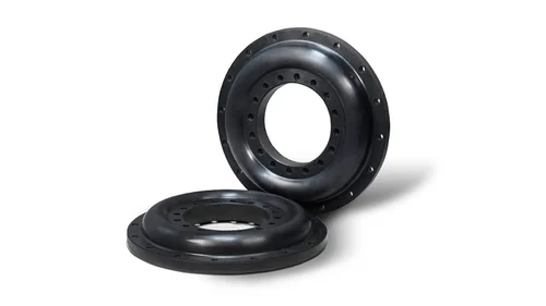
Role of Rubber Flexibility in Accommodating Misalignment
Rubber couplings are designed with a flexible element, usually made of elastomers, that plays a crucial role in accommodating misalignment between connected shafts. The flexibility of the rubber element allows it to deform and absorb angular, axial, and radial misalignments, providing several benefits:
1. Angular Misalignment: When the input and output shafts are not perfectly aligned in terms of angle, the rubber element can flex and twist, allowing the coupling to transmit torque even when the axes are not parallel.
2. Axial Misalignment: Axial misalignment occurs when the shafts move closer together or farther apart along their axis. The rubber element can compress or extend, adjusting the distance between the shafts without hindering torque transfer.
3. Radial Misalignment: Radial misalignment refers to the offset between the centers of the shafts. The rubber element can bend in response to radial displacement, ensuring that the coupling remains operational while accommodating the offset.
This flexibility not only enables the rubber coupling to handle misalignment but also helps prevent excessive stress on the connected machinery. By absorbing shock loads and distributing forces, the rubber element reduces wear and tear on components and minimizes the risk of premature failure.
In essence, the rubber’s flexibility in the coupling acts as a buffer against misalignment-induced stresses, contributing to smoother operation, improved longevity, and reduced maintenance in mechanical systems.


editor by CX 2023-10-07