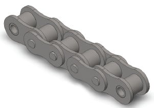
The following methods ought to be utilized to select chain and sprocket sizes, ascertain the minimum center distance, and determine the length of chain desired in pitches. We will generally use Imperial units (such as horsepower) on this section even so Kilowatt Capacity tables are available for each chain size inside the preceding part. The choice system is definitely the similar regardless of the units employed.
Phase one: Determine the Class from the Driven Load
Estimate which of the following ideal characterizes the ailment from the drive.
Uniform: Smooth operation. Minor or no shock loading. Soft start up. Reasonable: Usual or moderate shock loading.
Hefty: Extreme shock loading. Regular begins and stops.
Stage 2: Decide the Support Factor
From Table 1 beneath establish the proper Services Component (SF) for the drive.
Step three: Calculate Design and style Electrical power  Requirement
Design and style Horsepower (DHP) = HP x SF (Imperial Units)
or
Layout Kilowatt Electrical power (DKW) = KW x SF (Metric Units)
The Style Energy Requirement is equal to the motor (or engine) output energy times the Service Element obtained from Table 1.
Stage 4: Create a Tentative Chain Assortment
Create a tentative collection of the necessary chain dimension from the following manner:
one. If using Kilowatt electrical power – fi rst convert to horsepower for this phase by multiplying the motor Kilowatt rating by 1.340 . . . This can be important since the brief selector chart is shown in horsepower.
two. Locate the Design and style Horsepower calculated in phase 3 by studying up the single, double, triple or quad chain columns. Draw a horizontal line through this value.
3. Locate the rpm of the smaller sprocket over the horizontal axis of your chart. Draw a vertical line as a result of this worth.
4. The intersection on the two lines need to indicate the tentative chain selection.
Stage 5: Decide on the quantity of Teeth for that Smaller Sprocket
As soon as a tentative collection of the chain size is made we have to ascertain the minimum variety of teeth expected on the compact sprocket expected to transmit the Style and design Horsepower (DHP) or the Design and style Kilowatt Electrical power (DKW).
Step 6: Identify the number of Teeth for that Big Sprocket
Utilize the following to calculate the quantity of teeth for that substantial sprocket:
N = (r / R) x n
The number of teeth to the big sprocket equals the rpm of your small sprocket (r) divided by the desired rpm in the substantial sprocket (R) times the number of teeth around the tiny sprocket. If your sprocket is also big for your room available then several strand chains of the smaller pitch should be checked.
Phase seven: Identify the Minimal Shaft Center Distance
Utilize the following to determine the minimal shaft center distance (in chain pitches):
C (min) = (2N + n) / 6
The over is often a guide only.
Phase eight: Check out the Final Assortment
Furthermore be aware of any potential interference or other room limitations that may exist and adjust the assortment accordingly. In general probably the most efficient/cost eff ective drive employs single strand chains. This is often mainly because many strand sprockets are much more pricey and as might be ascertained by the multi-strand variables the chains turn out to be much less effi cient in transmitting electrical power as the amount of strands increases. It is actually thus usually best to specify single strand chains every time feasible
Stage 9: Establish the Length of Chain in Pitches
Make use of the following to determine the length of the chain (L) in pitches:
L = ((N + n) / 2) + (2C) + (K / C)
Values for “K” could be located in Table four on page 43. Recall that
C may be the shaft center distance offered in pitches of chain (not inches or millimeters etc). In the event the shaft center distance is acknowledged in the unit of length the worth C is obtained by dividing the chain pitch (within the exact same unit) by the shaft centers.
C = Shaft Centers (inches) / Chain Pitch (inches)
or
C = Shaft Centers (millimeters) / Chain Pitch (millimeters)
Note that anytime feasible it is most effective to utilize an even variety of pitches in order to stay clear of the use of an off set link. Off sets don’t possess the same load carrying capability as the base chain and really should be averted if achievable.
The Drive Chain Choice Procedure
Tags: